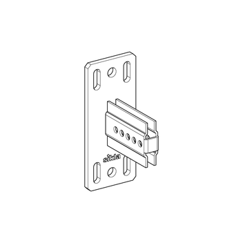
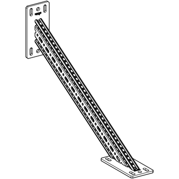
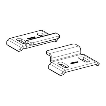
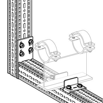
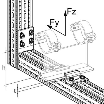
Guiding Bracket FW F LZ

Group

A705

Application

Using this Guiding Bracket it’s possible to guide Pipe Shoes with different plate thicknesses. The different versions of Type Z are suitable for the respective specified maximum plate thickness (t)and so additionally allow the absorption of lifting forces.

Scope of delivery

Delivery as set comprising 2 Guiding Brackets.

Installation

Installation on top of Beam Section TP F 80 repectively F 100 with 2 Self Forming Screws FLS F per Guiding Bracket, i.e. per set 4 Self Forming Screws have to be used altogether. You can find the Self Forming Screw in the siFramo chapters (section Siconnect).
For Type Z exists a clearance of 3 mm in the vertical z-axis. Please ensure a clearance of 3 mm in the vertical y-axis for all types.

Description

Technical Data

Type perm. load Fy
[kN]
perm. torque via Fy*
[kNm]
perm. load Fz
[kN]
FW F 80, all Types Z 1.9 0.4 5.0
FW F 80, Typ L 1.9
FW F 100, all Types Z 1.9 0.4 6.4
FW F 100, Typ L 1.9

* the torque is calculated by M = Fy x h, whereas the perm. load for Fy may not be exceeded. Dimension h refers from the middle of the pipe to the top of the base plate.
The perm. loads have been determined by load tests following DIN EN 13480-3 annex J.
The used Pipe Shoe has to be verified separately.

Material: Steel, HCP

* suitable for Sikla Pipe Shoes

Type t
[mm]
W
[kg]
Qty.
[set]
Part
number
FW F 80 Z 6 6 0.5 25 113628
FW F 80 Z 9 9 0.5 25 113629
FW F 80 Z 12 * 12 0.5 25 113630
FW F 80 Z 15 15 0.5 25 113975
FW F 80 L 0.5 25 113627
FW F 100 Z 6 6 0.6 25 113632
FW F 100 Z 9 9 0.6 25 113633
FW F 100 Z 12 * 12 0.6 25 113634
FW F 100 Z 15 15 0.6 25 113976
FW F 100 L 0.6 25 113631